

RichardM
-
Posts
183 -
Joined
-
Last visited
-
Days Won
25
Content Type
Profiles
Forums
Gallery
Calendar
Posts posted by RichardM
-
-
According to the manual !!
TRANSMISSION TEMPERATURE SENSOR
The TRS has an integrated thermistor that the PCM/TCM uses to monitor the transmission’s sump temperature. Since fluid temperature
can affect transmission shift quality and convertor lock up, the PCM/TCM requires this information to determine which shift schedule to operate in. The
PCM also monitors this temperature data so it can energize the vehicle cooling fan(s) when a transmission “overheat” condition exists. If the thermistor circuit
fails, the PCM/TCM will revert to calculated oil temperature usage.
CALCULATED TEMPERATURE
A failure in the temperature sensor or circuit will result in calculated temperature being substituted for actual temperature. Calculated temperature is a predicted
fluid temperature which is calculated from a combination of inputs:
² Battery (ambient) temperature
² Engine coolant temperature
² In-gear run time since start-upso check if fans are cutting in ??
Oil gets less viscous as it warms up .. I imagine this would cause slip rather than not changing up but I may be (and probably are) wrong.
If `the temp is out of range I would imagine you would get a OBD error code,although there is no mention of this in the 41TE section of the worksh*t manual .. check for error with key dance.
Also can find no mention of acceptable temp range - sorry.
Also, good to identify your vehicle as you may not have a 41TE box........
-
They won't work in series, may work in a parallel (think that's what you meant anyway )but suspect the GVs brain will detect this and diagnose it as a fault - also may blow the driver in IPM or fry the wiring.
-
Only too happy to supply diagrams if required... On the battery discharging overnight, this may be due to an old or underrated battery. Also when you've got a few moments check for excessive drain from the battery with every thing switched off. There is a great deal of information on the site regarding parasitic drain (quite often caused by a faulty audio amplifier) - If it is this just pull the fuse and check again. On the subject of the fifth door, there are reports of this on the site but have never heard how (or if) it was resolved. Pity you live so far away as I have a donor GV (2006) with a power rear door that works fine (died of gearbox failure), as bignev said this sounds like a precursor to the TCM providing another challenge. When I bought the donor I spent a bit of time trying to fix the gear problem - resolved the all gears lit up problem (wiring problem) - thought hey ho but did not resolve the gearbox problem - kept changing gear at will .. but that's another story.
Good luck with your project (don't want to be pessemistic but it's enough of a challenge keeping a normal GV on the road.. (Yes Bignev, I agree, there ain't no such thing as NORMAL with respect to the GV..
-
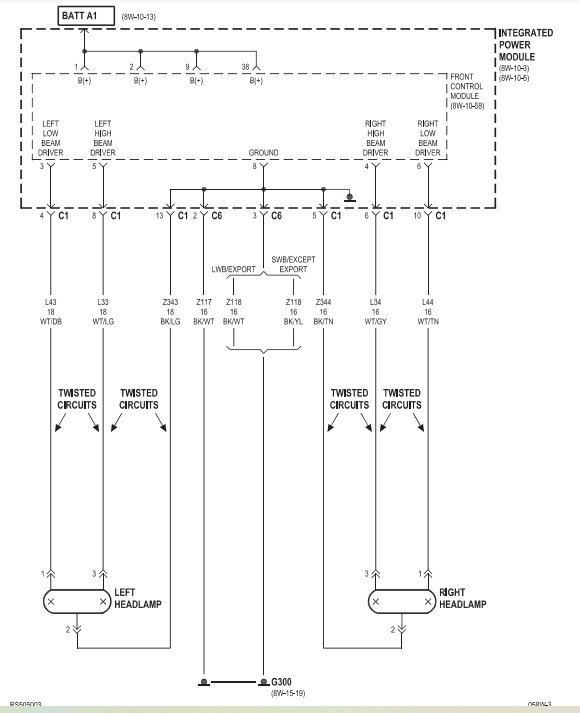
According to the workpoo manual fuses 1,2,3 control the front lights
1 - Front Fog Lamps
2 - left parking / turn lamp
3 right parking/ turn lamp & rear lamps( assume the parking lamps are also the front sidelights ?
Headlights are fed directly from the front control module (both high and dip
Bulbs blown ??
Switch dodgy ??
wiring damaged ??
let us know how you get on
-
Thanks to Ben for upload adjustment - picture of mirror switch now available !!
-
Welcome to the UK Chrysler forum, why not fill in the details of your vehicle ~ assume you own some kind of Chrysler, I think those of us that aren't hybernating are doing OK !
-
-
Sorry didn't motice the 6 speed auto bit...Ooops - check fluid level - again mileage / service history. Is it the same hot or cold - the engine / transmission - not the atmosphere. Sounds like luxury to have 6 speed auto but maybe 1 1/2 times the probles of a four speed ?
As far as I am aware there's no workpoo manual available for this model ?? - If it's anything like that for the Mk IV then you are not missing much.
Transfer the question to the GV 5 forum and see what happens
-
auto or manual (Ps) put queries in the Voyager forum - more likely to get a reply! = assume as you say selecting 1st gear it's manual - maybe clutch is on the way out - mileage ? service history ??
-
Sorry it took so long to reply - I normally go straight to the GV4 forum, didn't get any notification on this one -
Thankyou, well done !
-
Aha - isn't life amazing
-
Sorry I don't think I can help at all.
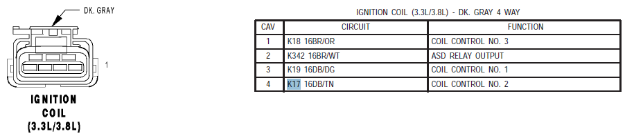
The circuit diagram for the V8 in the workpoo manual is totally different to your description and image. There is no BLUE connector on the coil circuit, there is no blue connector at all with a pink tab.
Coil Control No.1 - Pin 3 Ign Coil fed from pin 10 on the PCM K19 DB/DG Connector C2
Pin2 goes to Pin 3 on the IPM K342 BR/WT (Auto Shut Down) Connector C4
Coil Control No.2 -Pin 4 Ign Coil fed from pin 9 on the PCM K17 DB/TN Connector C2
Coil Control No 3 -Pin 1 Ign Coil fed from pin 7 on the PCM K18 BR/OR Connector C2
How the hell did you upload that image - I cann't load the smallest image at all !
-
Depending on how much you value the vehicle you could try drilling out the threaded section of the camshaft and helicoil it -WARNING may destroy the engine if not accurately done.
otherwise;
REMOVAL
(1) Remove cylinder head cover
(2) Remove camshaft position sensor and camshaft
target magnet(3) Remove timing belt
(4) Remove camshaft sprockets and timing belt rear cover
(5) Bearing caps are identified for location.
Remove the outside bearing caps first
(6) Loosen the camshaft bearing cap attaching fasteners
CAUTION: Camshafts are not interchangeable. The intake cam number 6 thrust bearing face spacing is wider.
(7) Identify the camshafts before removing from the head. The camshafts are not interchangeable.
(8) Remove camshafts from cylinder head.INSTALLATION
CAUTION: Ensure that NONE of the pistons are at top dead center when installing the camshafts.
(1) Lubricate all camshaft bearing journals, rocker arms and camshaft lobes.
(2) Install all rocker arms in original positions, if reused.
(3) Position camshafts on cylinder head bearing journals. Install right and left camshaft bearing caps No. 2 – 5 and right No. 6. Tighten M6 fasteners to 12 N·m (105 in. lbs.) in sequence shown in (Fig. 28).
(4) Apply Mopart Gasket Maker to No. 1 and No. 6 bearing caps (Fig. 29). Install bearing caps and tighten M8 fasteners to 28 N·m (250 in. lbs.).
NOTE: Bearing end caps must be installed before seals can be installed.
(5) Install camshaft oil seals (Refer to 9 - ENGINE/CYLINDER HEAD/CAMSHAFT OIL SEAL(S) - INSTALLATION).
(6) Install camshaft target magnet and camshaft position sensor.
(7) Install cylinder head cover (Refer to 9 -ENGINE/CYLINDER HEAD/CYLINDER HEAD COVER - INSTALLATION).
(8) Install timing belt rear cover and camshaft sprockets (Refer to 9 - ENGINE/VALVE TIMING/ TIMING BELT COVER(S) - INSTALLATION).
(9) Install timing belt (Refer to 9 - ENGINE/ VALVE TIMING/TIMING BELT AND SPROCKETS - INSTALLATION).CYLINDER HEAD COVER(From the workpoo manual - sorry images are impossible to load due to stupid size restriction imposed on the forum
-
-
sorry but the file upload for mirror switch too big to load
-
Ther is no relay for the mirrors only a fuse (No. 18.. 15A
Mirrors (if you have memory seats there is another controller buried somewhere (under the seat ?)
ah hah - Remove the appropriate seat from the vehicle
and place it on a clean work surface, (Refer to 23 -
BODY/SEATS/SEAT - REMOVAL).
(3) Remove the Memory Seat/Mirror Module
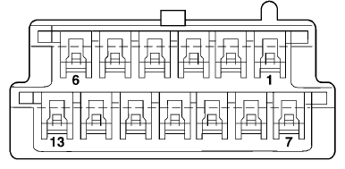
(MSMM) mounting fasteners (if equipped).SWITCH CONNECTOR 12 Volts Ground MIRROR REACTION Right Left PIN 12 PIN 6 UP PIN 7 PIN 6 Left Pin6 Pin 12 Down Pin 6 Pin 7 Right PIN 13 Pin 1 Up Pin8 Pin 1 Left PIN 1 Pin 13 Down PIN 1 Pin 8 Right refer to Mirror connector switch image attached - Using two jumper wires:
Connect one to a 12-volt source
Connect the other to a good body ground
Refer to the Mirror Test Chart for wire hookups at the switch connectoranother answer follows with switch wirig details
-
Was previously able to download images to assist in diagnosis of problems (Mk 4 GV) now restricted to 18.1 KB - spent an hour this morning trying to convert wiring images to this size but failed.. Why has this restriction been initiated & can it at least be uplifted to 200K PLEASE - these days that's not unduly large !
-
any success on the search with the new vin ?
-
Assuming this is a late registered Mk 4, there is only one relay feeding the mirrors(according to the workpoo manual (no did not spell it wrong), if it's a Mk 5 then don't know.
Possibility the switch is at fault. Tried to upload an image from the manual but 18.iKb doesn't permit !
With respect to the park assist suggestion 1 - remove battery negative lead for 10 minutes... 2- clean each sensor individually with soapy water ?
-
Only just caught this query whilst browsing. I would suggest you post further queries in the Grand Voyager V forum. Question 1 is what OBD codes are you getting, these codes should at least point in the general area of the problem & take it from there (and then repost with these codes in the correct forum )
Best of luck - Richard
-
Thanks for the reply but have had the injectors checked, they are apparently all OK.
-
There are websites offering to supply a pin for the vin, tried a couple on your behalf both said they don't recognise the vehicle.. not suprising with a GV...
You could try other (pay for results) sites but I would be wary of spending a fortune on unproven sites.
I believe you would then need the DRB111 tool to reprogram the SKIM ????
-
Again, back to the lurid story of failure to start when the engine is hot (well not hot as in overheating, just hot as in at running temperature, that is to say between 1/4 and 1/2 on the temperature gauge).
Start the car in the morning (today it was -6 Celsius this morning, key in, wait for glow plug light to go off, start (turns over five or six times), fires up and idles perfectly. Drive along, accelerate etc. no problem.
Drive 10 - 15 miles ( at -4 Celsius) Park up for 5 - 20 minutes, gauge is just off 0) Start up after glow plugs off (1 - 2 sec) away we go.
Park up for 6 hours, same - no problem.
Drive long enough to get engine hot, difficult to do at this time of year! Park up (say 1/2 hour), engine still hot, warm no way it will start without a blast of cold start, then drive, accelerate all tikety-boo.
Only error (repetitive) is P1130 - fuel pressure too high, too low. (Very helpful).
So over the last two years or so, pressure relief valve changed, pressure sensor changed, pressure solenoid changed, injectors checked So what else can it be ?
I read a post on the JEEP SITE , sighting the non return valve (FUEL FLOW BACK VALVE (Yank speak)) as a possibility ?Has anyone replaced this pipe assembly, if so easy, hard, what am I going to bugger up ? (I have a spare car with a good engine (knackered gear box or associated electronics)
All replies gratefully received but it ain't normal fuel starvation - she accelerates like (expletive).
Doesn't normally stall - did a couple of times in the past but I put that down to me changing things and not bleeding her properly.Pipe assembly thingumy attached -no it's not fails claiming file size too big (17.1Kb ??) - sorry
-
I think it would be useful to all members, subscribers and visitors if, when a problem is posted and resolved that the solution should be posted. That way anyone else with the same problem may be presented with an immediate solution.
A quick 'Thanks (who ever) that's solved it) would suffice, or, if the solution was something else then a quick note on what the solution was would be great.


Auto Transmission Specialist
in Voyager 4th Generation (2001-2007)
Posted
This info is given with no personal knowledge of the gentleman, only gleened from the Facebook Grand Voyager / Town and Country Group (https://www.facebook.com/groups/696452663776017)
Tomsz Kulak appears to be an excellent mechanic with detailed knowledge of the GV.
He appears to travel where ever - don't know his costs or anything eles about him but if everything else fails it may be worth contacting him through facebook !
Again I must emphasize, I have no personal knowledge of this man nor can I vouch for his apparent reputation on the site.